Can ship immediately
Due to market price fluctuations,if you need to purchase or consult the price.You can contact us or emial to us: brenda@hongda-ic.com
1. Describe
The TDA7110FHTMA1 is a single-chip ASK/FSK transmitter that operates in the 433 ... 435 MHz frequency band. The IC is highly integrated and requires few external components. The device contains a fully integrated PLL synthesizer and a high-efficiency power amplifier for driving the loop antenna. Special circuit design and unique power amplifier design are used to save current consumption, thus extending battery life. Other features include power-down mode and divided clock output.
2. Feature
1. Fully integrated frequency synthesizer
2. VCO with no external components
3. ASK and FSK modulation
4. Frequency range 433 ... 435 MHz
5. High efficiency power amplifier (typically 10 dBm)
6. Low supply current
7. Supply voltage range 2.1 ... 4 V
8. Temperature range -40 ... +85°C
9. Power-down mode
10. Crystal 13.56 MHz
11. FSK switch
12. Divided clock output of µC
13. Low number of external components
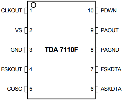
3. Pin configuration
4. Application
1. Keyless entry system
2. Remote control system
3. Alarm system
4. Communication system
5. Application Tips for Crystal Oscillators
When using the specified crystal, the crystal oscillator turn-on time is less than 1 millisecond. For this purpose, the NIC oscillator type is implemented in the TDA7110FHTMA1. The input impedance of this oscillator is a negative resistance in series with the inductor. So the load capacitance of crystal CL (specified by crystal supplier) is converted to capacitance Cv
6. Application Tips for Power Amplifiers
The power amplifier operates in high-efficiency class-C mode. This mode is characterized by pulsed operation of the power amplifier transistors at a current flow angle θ<<π. A frequency selective network at the amplifier output delivers the fundamental frequency component of the collector current pulse spectrum to the load. The resonant circuit L//C//RL in parallel with the output impedance of the transistor should be at the operating frequency of the transmitter.
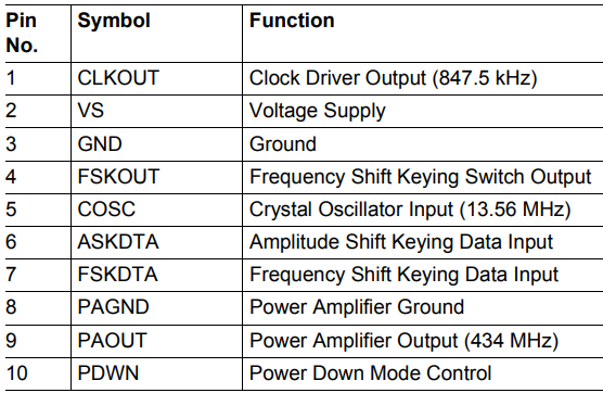
7. Pin Description