
Can ship immediately
Due to market price fluctuations,if you need to purchase or consult the price.You can contact us or emial to us: brenda@hongda-ic.com
1. Description
The DRV110APWR device is a PWM current controller for solenoids. The device is designed to regulate the current with a well-controlled waveform to reduce power dissipation. The solenoid current is ramped up fast to ensure opening of the valve or relay. After initial ramping, the solenoid current is kept at a peak value to ensure correct operation, after which the current is reduced to a lower hold level to avoid thermal problems and reduce power dissipation. The peak current duration is set with an external capacitor. The peak and hold levels of the current ramp, as well as the PWM frequency, can independently be set with external resistors. External setting resistors can also be omitted if the default values for the corresponding parameters are suitable for the application. The DRV110 device has an internal Zener diode that limits the supply at VIN to VZENER for applications that require a higher supply voltage. Using the internal Zener, the DRV110 can be powered from 120-V and 230-V AC supplies through a rectifier and currentlimiting resistor. High DC voltages such as 48-V can also be accommodated this way.
2. Features
1. Internal Zener Diode on Supply Pin for HighVoltage Operation
– 120- and 230-V AC Supply Through Rectifier and RS Resistor
– 24-V, 48-V, and Higher DC Supply Through RS Resistor
2. Drives an External MOSFET With PWM to Control Solenoid Current
– External Sense Resistor for Regulating Solenoid Current
3. Fast Ramp-Up of Solenoid Current to Ensure Activation
4. Solenoid Current is Reduced in Hold Mode for Lower Power and Thermal Dissipation
5. Ramp Peak Current, Keep Time at Peak Current, Hold Current, and PWM Clock Frequency Can Be Set Externally. They Can Also Be Operated at Nominal Values Without External Components.
6. Protection
– Thermal Shutdown
– Undervoltage Lockout (UVLO)
7. Optional STATUS Output
8. Operating Temperature Range: –40ºC to +125ºC
9. 8-Pin and 14-Pin TSSOP Package Options
3. Applications
1. Electromechanical Drivers: Solenoids, Valves, Relays, Contactors, Switchgear, Pneumatics
2. White Goods, Solar, Transportation, Smart Grid, Power Distribution
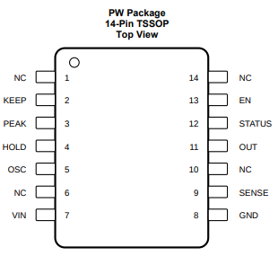
4. Pin Configuration
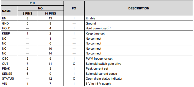
5. Pin Functions
6. Feature Description
The DRV110 controls the current through the solenoid as shown in Figure 2. Activation starts when EN pin voltage is pulled high either by an external driver or internal pullup. In the beginning of activation, DRV110 allows the solenoid current to ramp up to the peak value IPEAK and it regulates it at the peak value for the time, tKEEP, before reducing it to IHOLD. The solenoid current is regulated at the hold value as long as the EN pin is kept high. The initial current ramp-up time depends on the inductance and resistance of the solenoid. Once EN pin is driven to GND, DRV110 allows the solenoid current to decay to zero.
7. PWM Current Control
The current control loop regulates, cycle-by-cycle, the solenoid current by sensing voltage at the SENSE pin and controlling the external switching device gate through the OUT pin. During the ON-cycle, the OUT pin voltage is driven and kept high (equal to VIN voltage) allowing current to flow through the external switch as long as the voltage at the SENSE pin is less than VREF. As soon as the voltage at the SENSE pin is above VREF, the OUT pin voltage is immediately driven low and kept low until the next ON-cycle is triggered by the internal PWM clock signal. In the beginning of each ON-cycle, the OUT pin voltage is driven high and kept high for at least the time determined by the minimum PWM signal duty cycle, DMIN. Because the current sense is done by comparing the voltage at the SENSE pin to a reference voltage, the DRV110 device acts like a hysteresis controller. When the device acts like a hysteresis controller, it can make the PWM frequency and duty cycle appear uneven for some solenoids .

